AURORA BOREALIS Ltd.
Equipment for the complete cycle of waste management
Own production
Engineering and mounting
Warranty and service
Equipment for the complete cycle of waste management
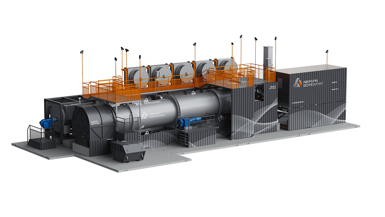
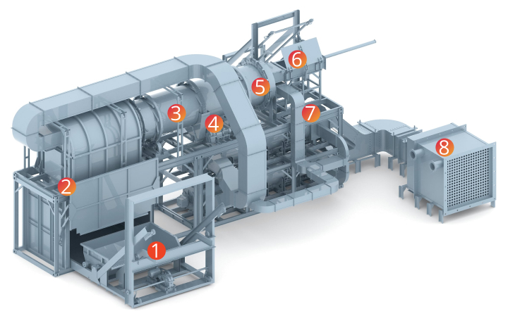
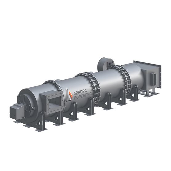
We have made for you our best furnace with a spinning drum, automatic control and self-measurement of emissions.
We manufacture incinerators for thermal waste decontamination, gas cleaning units and ceramic heat exchangers.
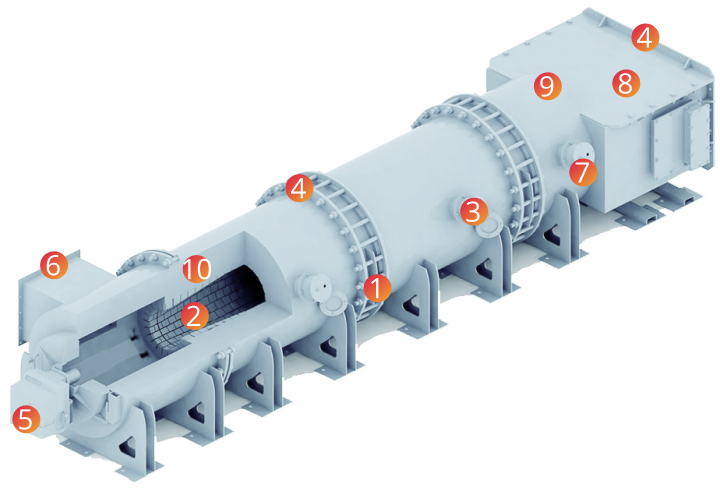
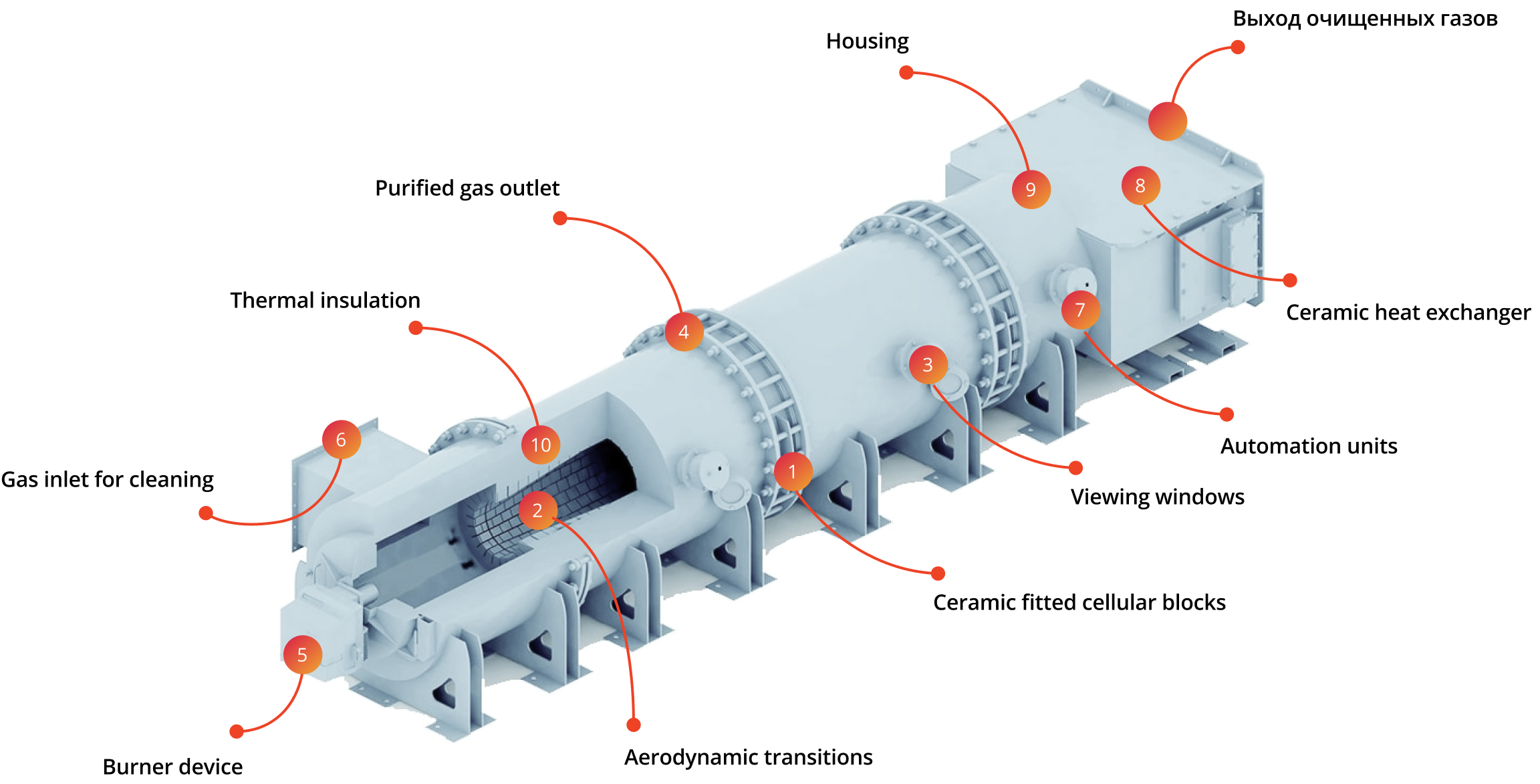
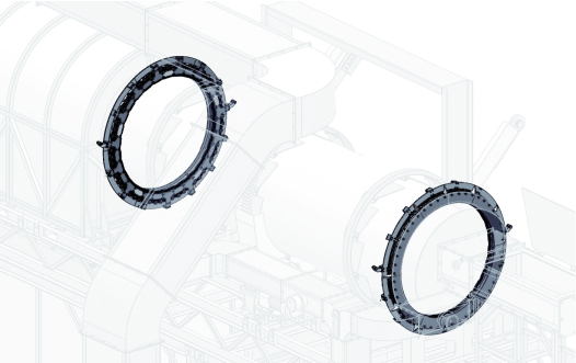
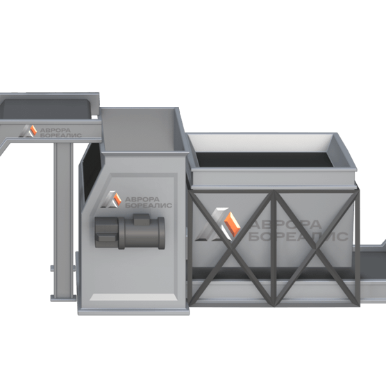
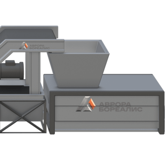
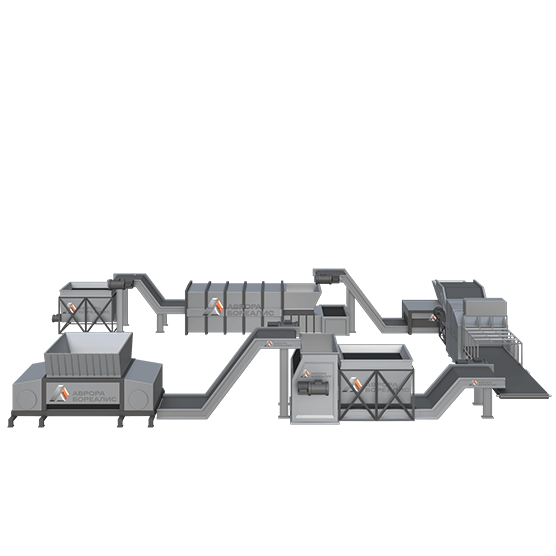
Our products are manufactured using unique technology of oxidative design in ceramics. Plant consists of a modified incinerator and a unit for high-temperature cleaning of flue gases. Combustion of soot and organic compounds occurs in the channels of the ceramic honeycomb blocks; a ceramic heat exchanger is installed to cool the flow and recover the heat.
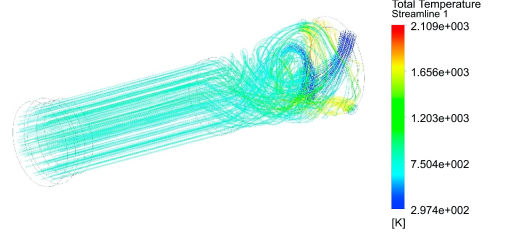
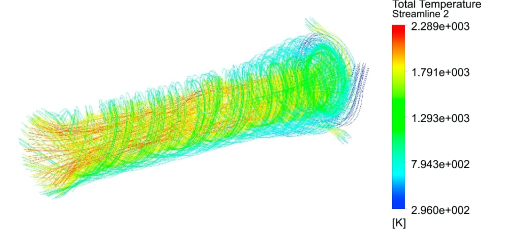
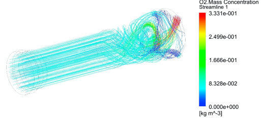
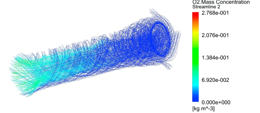
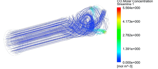
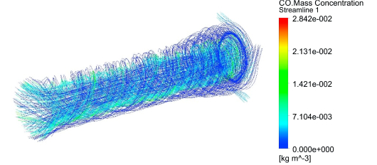
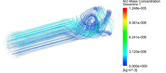
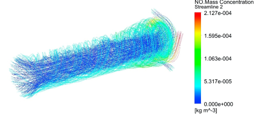
From the simulation, it can be seen that, due to the poor distribution of the components inside the “classical” afterburner, incomplete oxidisation of contaminants occurs. At the same time, in this afterburner, the excess of oxygen is high on average. However, there are local zones and “cold corridors” where there is not enough oxygen. It is in these places that pollutants “slip” through.Due to the uneven temperatures, nitrogen oxides are additionally synthesised.
On the other hand, the ceramic cellular blocks used in the Aurora Borealis afterburners both completely eliminate the likelihood of leakage of contaminants and equalise the temperature field inside the device
If you make a dynamic calculation in which the “cold corridors” change their position several times per second, then the advantages of the Aurora Borealis afterburner become even more obvious.
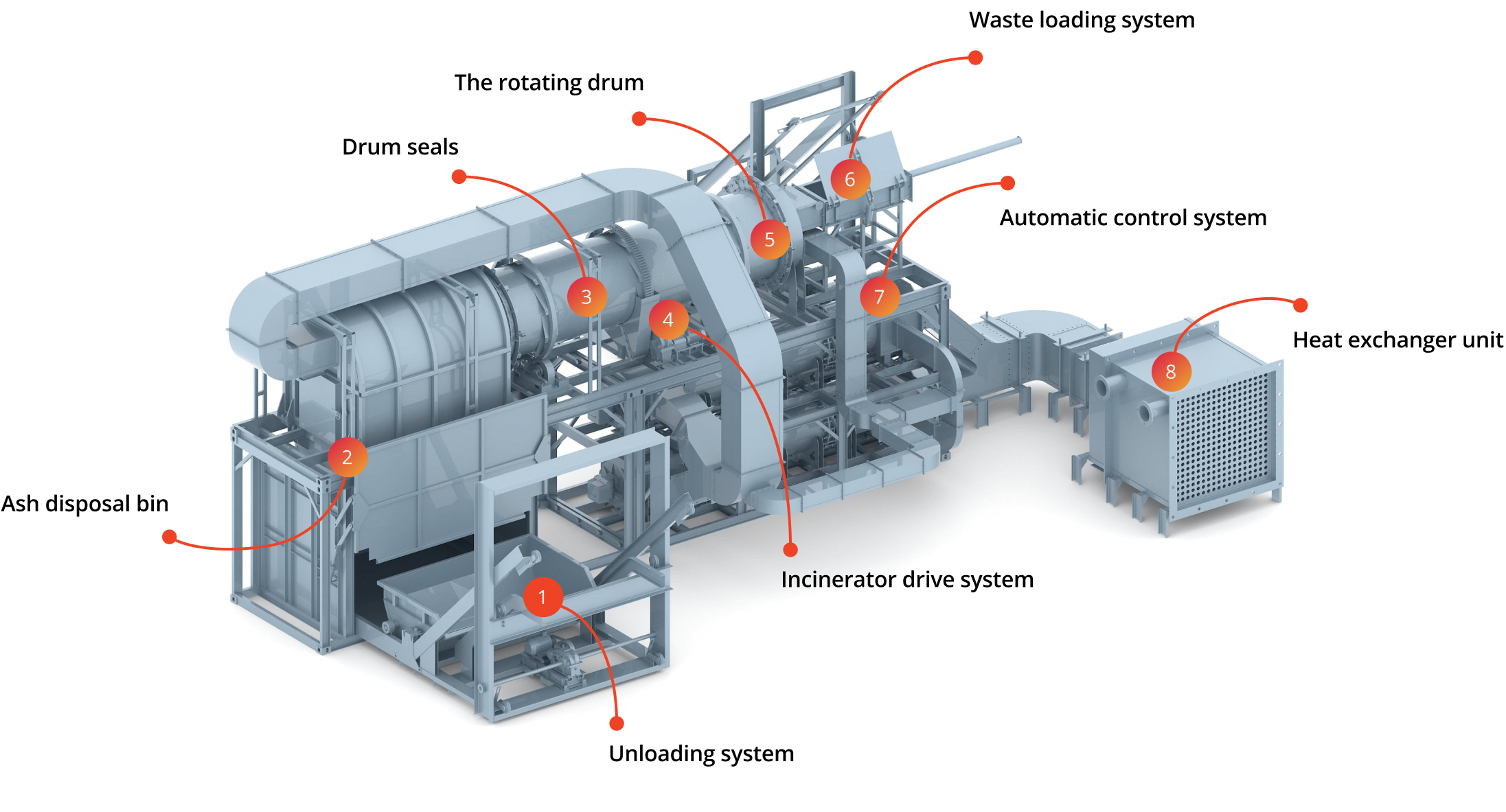
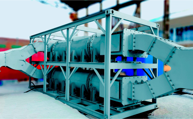
The only incinerator that uses a heat exchanger that heats the air necessary for combustion, our incinerator is the most energy efficient due to the tightness of loading, unloading and sealing units. The use of modulated burners results in greater fuel economy, and the use of automated monitoring systems, including gas analyzers, which work along the entire combustion cycle, allows working with a minimum excess of oxygen
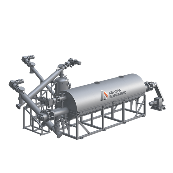
Our products use the most reliable and versatile principle of emissions cleaning - afterburning. Any organic components contained in the gases to be cleaned are subject to purification with an efficiency of >99%.
In a temperature of about 1000 ° C and the presence of oxygen, the components of the emission are completely oxidised. The result is pure carbon dioxide CO2 and water vapor H2O. The process takes place with an optimal excess of oxygen and in a uniform temperature field, thanks to which the synthesis of nitrogen oxides is minimal.
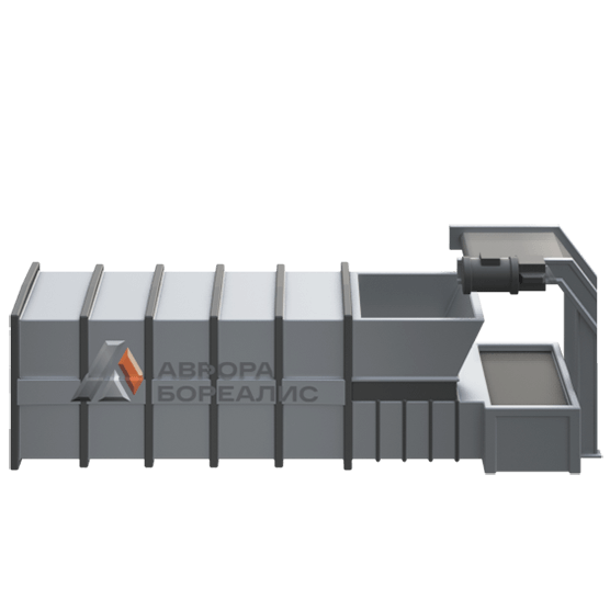
A wet scrubber is optionally used for cleaning acidic gases (CO2 and HCL)


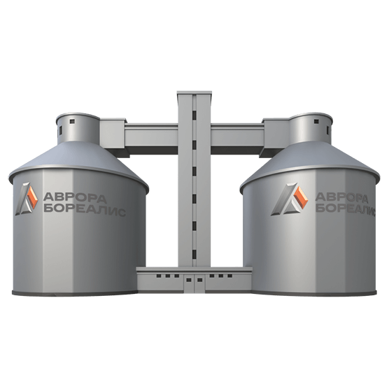
In the sediment chamber, due to the increase in the conditional passage, the speed of movement of the flue gases is significantly reduced. As a result, the number of settling particles increases.
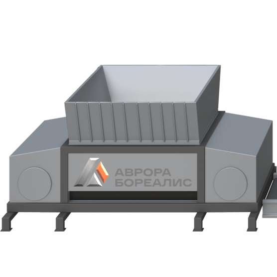
The design of the bunker provides: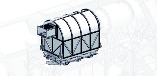
Fill out the simple form below and we will answer all your questions.
![]()
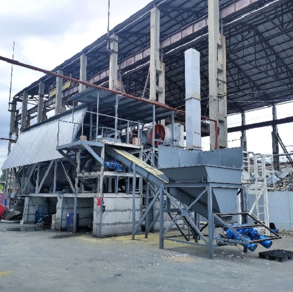
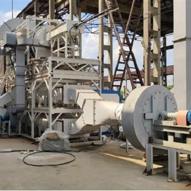
Начиная с весны 2022 года идет строительство нового завода по производству современного оборудования для обращения с отходами.
Инженеры компании неустанно трудятся над проектированием и тестированием нового высокотехнологичного оборудования, которое помогает избавить страну от вредных выбросов.
За последние полгода компании удалось открыть 2 новых цеха, а штат вырос в 3 раза. И будет расти дальше, наращивать производство. Здесь классные коллеги-единомышленники и интересные проекты. Мы не просто инновационная компания - это реальный сектор экономики, тяжелое машиностроение, здесь все серьезно!
Компания всегда готова принять в свой теплый коллектив новых специалистов, особенно востребованы инженеры-конструкторы и инженеры-конструкторы АСУ ТП.
Все вакансии размещены на : https://yaroslavl.hh.ru/employer/5953726
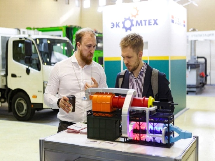
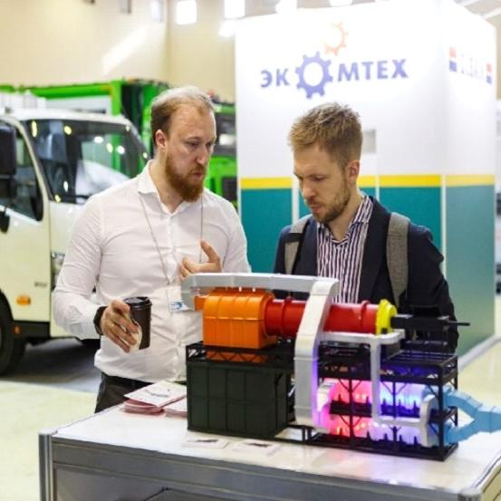
WASMA 2022- это крупная отраслевая выставка по технологиям переработки мусора и водоочистки.
На выставке WASMA 2022 c 21 по 23 марта компания приняла участие со оборудованным стендом. В качестве выставочного экспоната был представлен специально разработанный макет с подсветкой. Компания привлекала внимание 90% участников выставки.
Компания значительно обновила модель, внедрила двойные шнеки, внедрила шнек на зону выгрузки, добавила датчик органических выбросов, появился графический интерфейс – то есть сейчас это установка, которая управляется с планшета. Также укоротила дымоход печи с 20 метров до 1. Это позволило снизить себестоимость продукта и убрать еще большой список проблем без потери качества.
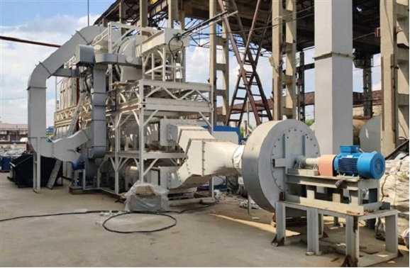
Резидент Сколково – компания ООО «Аврора Бореалис» 08 февраля 2021 г. получила положительное заключение государственной экологической экспертизы на инновационную установку по утилизации и обезвреживанию отходов с узлом глубокой очистки отходящих газов серии «Аврора».
В установку встроена уникальная система очистки отходящих дымовых газов, которая позволяет очищать выброс на 99,9%. Уровень выброса по основным маркерным веществам ниже европейских норм в 5 раз. Сжигание сажи и органических соединений происходит в каналах керамических сотовых блоков собственного производства. Блоки нагреваются до 1000 градусов и все органические выбросы сгорают, проходя через них. Блоки легко чистятся и имеют долгий срок службы.
Установка может утилизировать от 1 до 5 тонн отходов в час с 2 по 5 класс опасности. Перечень ФККО включает более 4000 категорий отходов.
Максимальное сохранение тепла в установке достигается за счет полной теплоизоляции компонентов установки в том числе за счет футеровки огнеупорным кирпичом. Это позволяет избегать лишних затрат на топливо и достигать высоких рабочих температур, работу в непрерывном цикле.
Получая данные с 8 точек анализа состава газов, с 10 точек контроля разряжения и 15 точек измерения температуры, система управления самостоятельно ведет подстройку модулируемых горелочных устройств, расхода первичного и вторичного воздуха, тяги и управляет процессом загрузки.
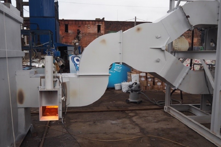
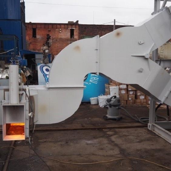
Для мусорного полигона Скоково, находящегося под Ярославлем, компанией ООО «Аврора Бореалис» разработана новая технология сжигания свалочного газа.
Директор компании - Александр Климов сообщил, что уровень очистки газа удалось повысить до 99%.
Проект получил название на латинском — «Аврора Бореалис», что переводится как «северное сияние».
Технология подходит для различных сфер использования: очистки дымовых газов от мусоросжигательных установок, дожигания попутных газов при нефтепереработке, очистки выбросов сталеплавильного производства при переработке лома и сжигании свалочного газа на полигонах захоронения ТБО.
Новая технология будет испытана на установке по термическому обезвреживанию медицинских и промышленных отходов фирмы «Биотерм».